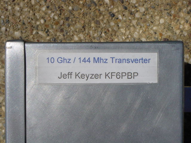
Jeff Keyzer, KF6PBP
For some time now, the San
Diego Amateur Radio Microwave Group has been converting Qualcomm
10GHz transverters used in the old Ku-band OmniTRACS
system to amateur radio use centered around 10.368GHz. I have been convinced
by a friend of mine and a member of the group, Tony (KC6QHP), to do the
conversion simultaneously with Shaun (KD6AZU), another UCSD
student and Wireless Communications
Club member. In the end we hope to have two newly converted transverters,
which, when combined with Tony's existing station, makes three 10GHz rigs
we can play around with. In order to document and share the conversion
effort, I have created this page and will update it periodically as progress
is made.
News:
8/27/00
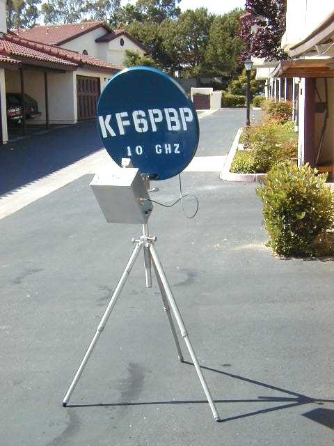
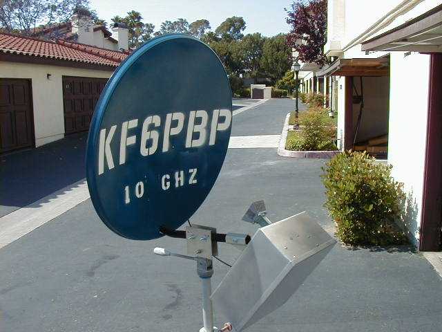
5/23/00 - The weekend before last, Tony and I put everything in a nice aluminum box and mounted the box and dish to a tripod given to me by Royce, KF6PEO. (Royce also made the box, which turned out extremely well. Thanks Royce!) Over this past weekend Tony and I painted the dish and put my callsign on it. Now people will stop asking me what Airlan (originally written on the dish) means and start asking "KF6PBP? 10 Ghz?" instead! The whole assembly has been tested extensively around town and works very well. I'm almost ready for contesting!
5/2/00 - Finally, I have made an update to this page! Due to a light class load during my final quarter as an undergraduate at UCSD, I have had time to put a lot more work into all of my microwave projects. The 1 watt X-band power amplifier has been tuned, the mixer board installed, a new 992 MHz filter installed, and the whole system has been thrown together enough to be usable.
It works! I am now active on 10 GHz during the weekly the San Diego Microwave Group net using a simple horn antenna. The LOS path from school to the SD X-band repeater is about 30 miles and signals are always full quieting.
Note: Most recent progress is highlighted.
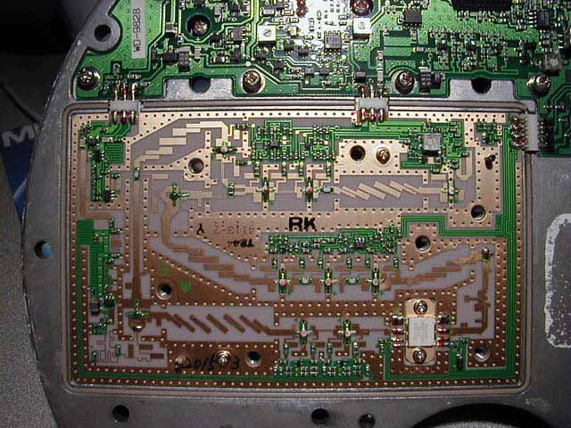
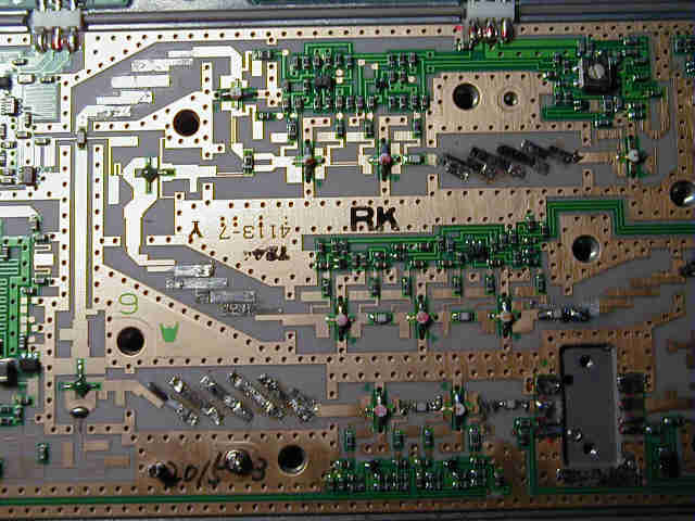
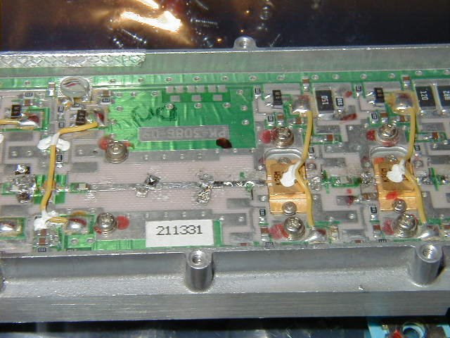
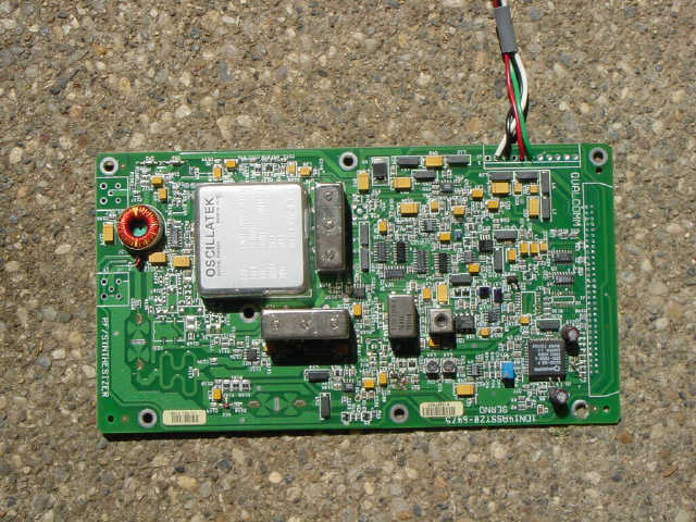
Underneath the milled aluminum cover is a teflon circuit board covered
with microstrip and microwave components.
10GHz subsection - Image 1
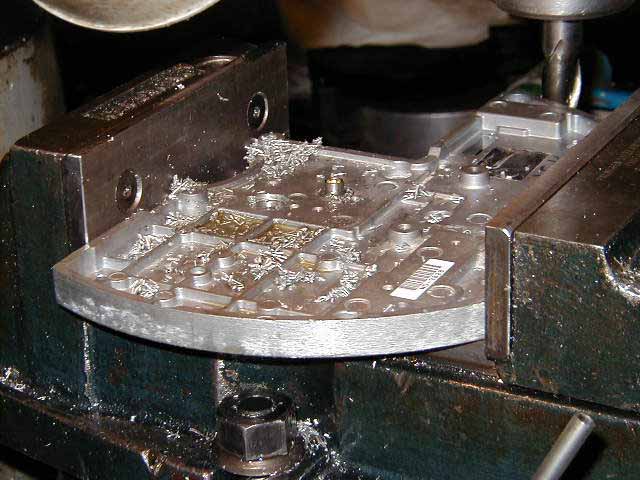
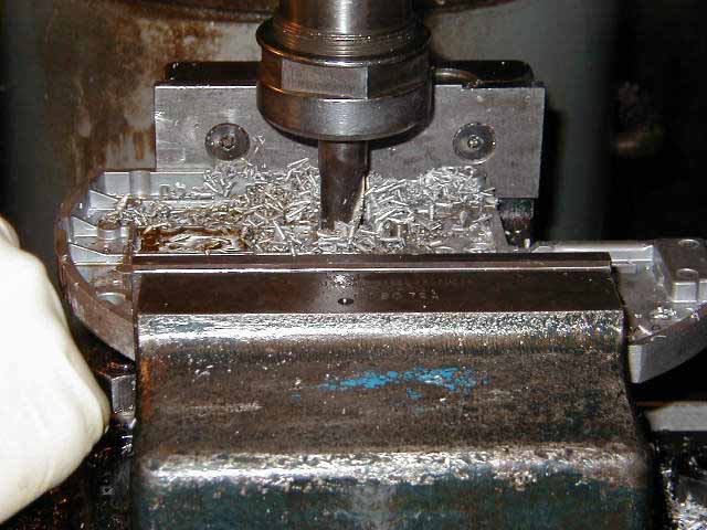
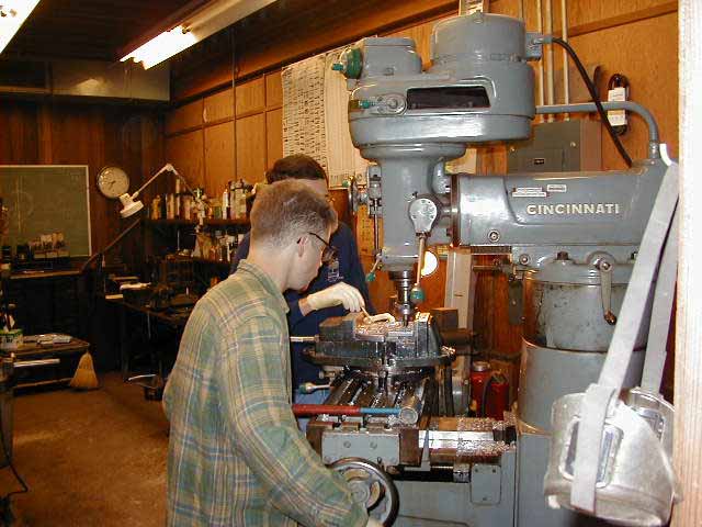
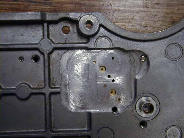
Milling the Transverter Chassis: Image
1, Image 2, Image
3
The final result: Image
1
(Looks pretty good, eh?)
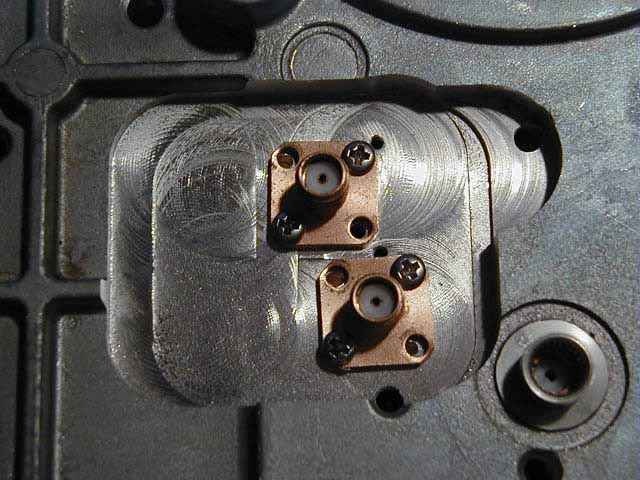
3/9/99 - The SMA connector mounting holes were drilled and tapped, and
the connectors mounted.
SMA Connectors Mounted - Image
1
Board with cuts and SMA connector center pins: Image 1
5/5/99 - After receiving a completed transverter from Kerry to use as a reference, I made the last of the modifications to the 10GHz section. These mods included one more cut and a few tuning stubs at various locations on the board.
5/13/99 - The synthesizer modifications have been completed. This entailed lifting several pins on the Qualcomm PLCC surface mount synthesizer chip and soldering one of those pins to ground. This programs the synthesizer for a 2272MHz VCO, which is multiplied and mixed to yield the 10.368MHz desired transverter output. Eventually I hope to put up a block diagram and theory of operation section for the benefit of those not involved with the SD Microwave Group.
5/2/00 - Here is some more info from Kerry on the synthesizer mods:
Synthesizer programming:
Lift pins 4,7,8,9,10,13,14,21,22
Tie pin 10 to pin 17 (15,16,17 are all ground)
Add (2) 3000 pF caps to reference supression filter
Add (1) 1000 pF cap to reference supression filter
Add two 0.5 pF caps in parallel to lower VCO frequency.
The caps were added to various locations around the synthesizer, someday I may get a good picture online.
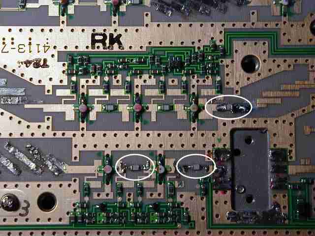
The 10GHz subsection with filter and capacitor mods - Image 1
A closeup of the added capacitors - Image 1
A closeup of one of the microstrip filters - Image 1
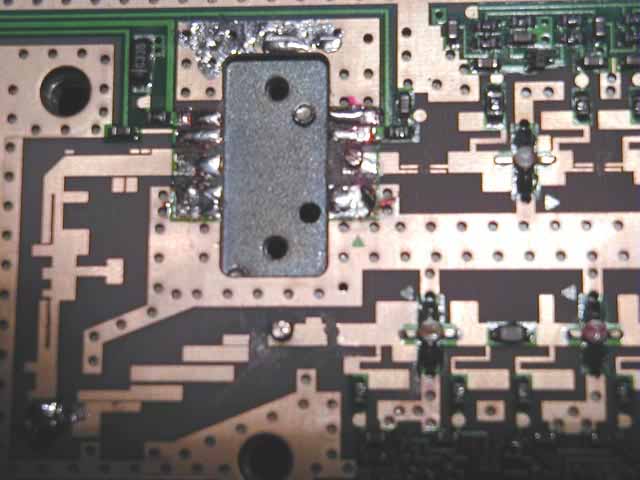
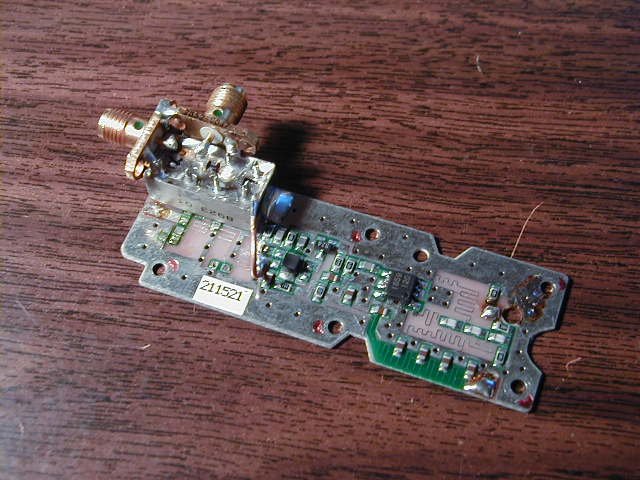
The 1st IF mixer board - Image 1
The PA had to be tuned to 10.368 GHz before it could be used in my setup. This procedure took a few hours and involves removing all tuning stubs from the microstrip on the board, then sliding a small square of thin copper attached to a toothpick along the microstrip lines until the maximum output power can be reached for a given input. A similar piece of copper is then soldered in that location and the process is repeated. Chuck WB6IGP has written an article describing this procedure. The result is a PA that gives just short of a watt out for 1 mW in and has about 29.5 dB gain.
The PA and power supply - Image 1
A closeup of the PA showing some tuning stubs I added - Image 1
The bottom of the PA showing SMA input/output - Image 1
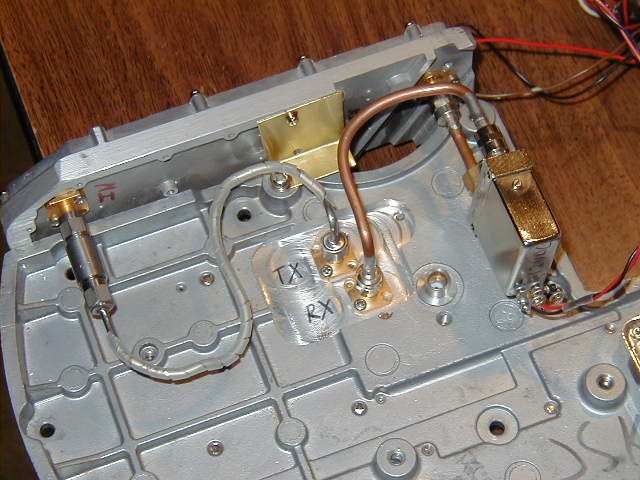
Added SMA connectors for 992MHz IF and 10MHz reference to transverter.
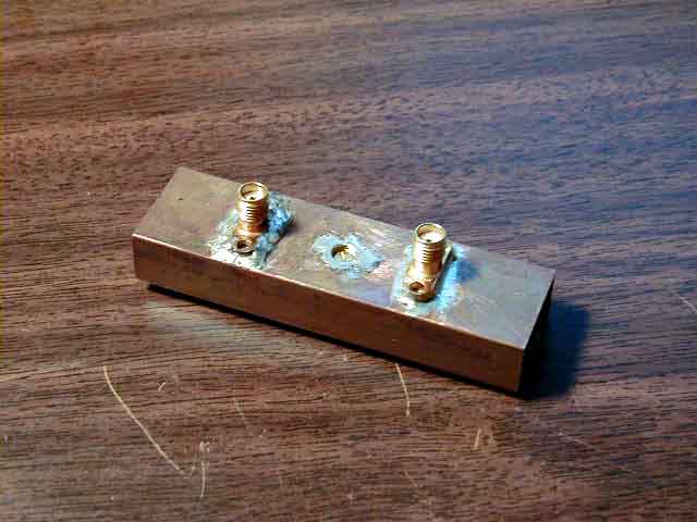
5/20/99 - Tony assisted me in producing a waveguide type bandpass filter, designed to pass
the 992MHz IF while rejecting the LO of 1136MHz and the 1136MHz+144MHz second image produced by the mixer board.
It's not beautiful, but it works! - Image 1
5/2/00 - The waveguide filter will not be used in the final system. Instead, a 992 MHz helical filter will be used. It is much smaller and lighter but performs the same function.
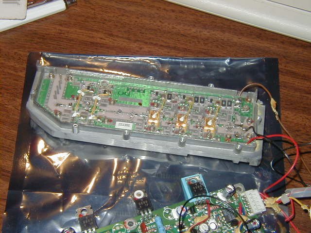
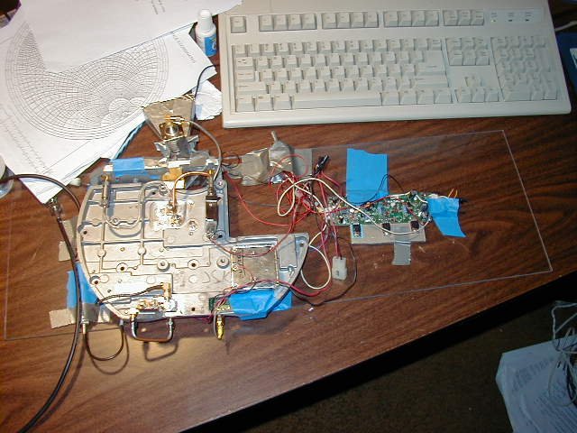
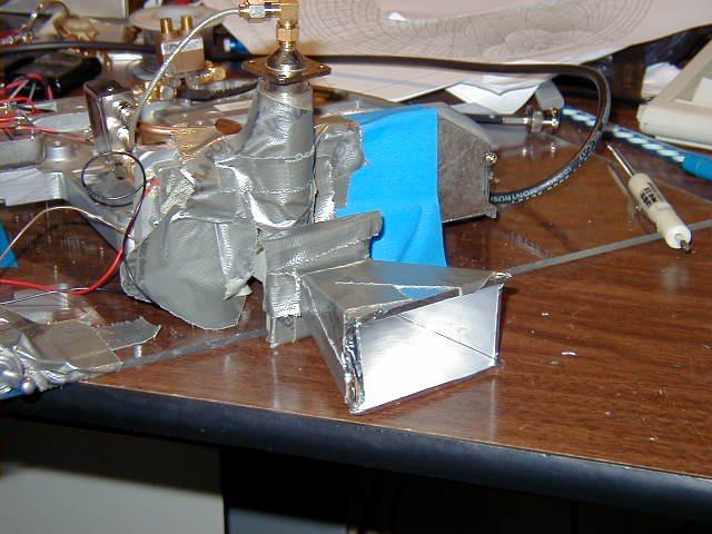
5/2/00 - It works! Apparently the problems at Kerry's last year turned out to be a bad cable in the test setup. The tuned PA was attached to the transverter by drilling and tapping a couple holes for screws. I wired up the PA, T/R coaxial relay, 992 MHz filter, 10 MHz TCXO, and PA power supply in order to do some tests. The temporary test setup is duct taped to a sheet of plexiglass to give me a convenient way to carry things around over the next few weeks. A friend is currently making an aluminum box to put the whole thing in. A feed still needs to be constructed. The box will also need to be mounted to a dish and tripod. This may end up being the most difficult part of this project!
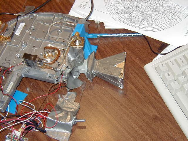
Upon throwing everything together, I desperately needed a temporary antenna. For the moment I am using an SMA to WR-90 transition and a horn made of cardboard and aluminum foil that Tony made for me. It works surprisingly well and allows me to work the SD X-band repeater from the third floor of EBU-2 at UCSD without any problems.
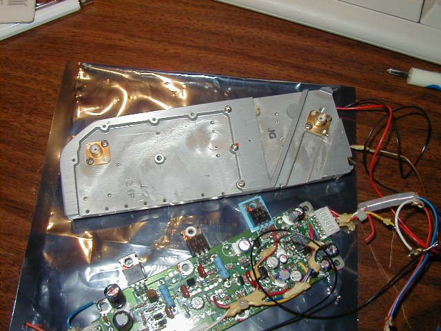
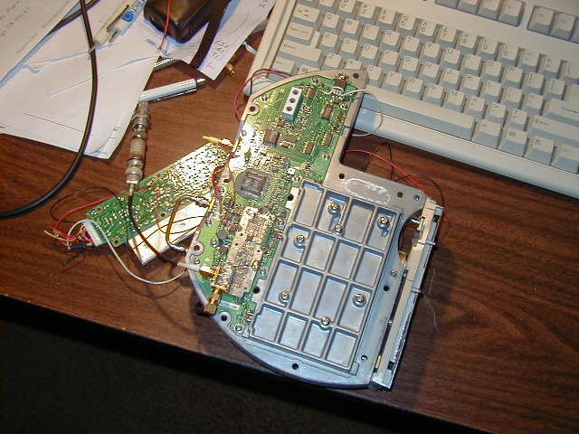
The transverter and PA - Image 1, Image 2
The "bottom" of the transverter showing the installed mixer board - Image 1
The duct tape and plexiglass mess I have made - Image 1
The cardboard and aluminum foil antenna - Image 1, Image 2
(Yes, the polarization on the horn is wrong - this took a few minutes to figure out when I
couldn't hear the repeater but could hear the beacon at the same location!)
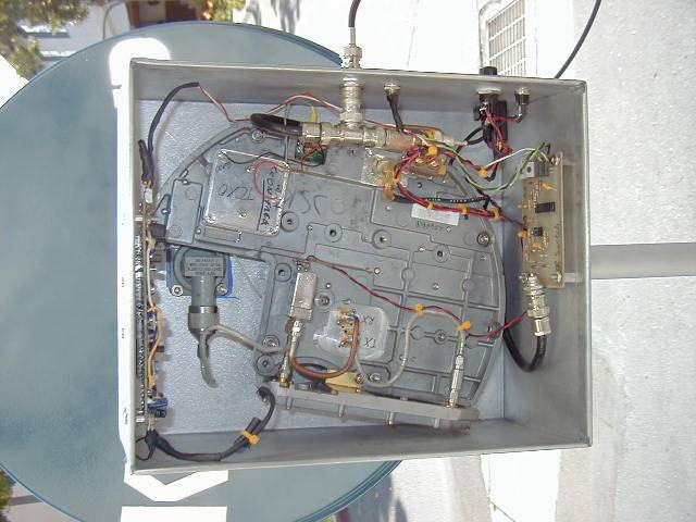
5/23/00 - The transverter has been mounted in an Aluminum box and the box and dish mounted to a heavy duty tripod. I am now using another offset feed parabolic dish purchased for $15 at Murphy's Surplus in El Cajon. It was originally used for a 2.4 GHz low power local area network and has a much better shape than the DirecPC dish I originally was going to use.
The newly painted dish and transverter box mounted to my tripod -
Image 1
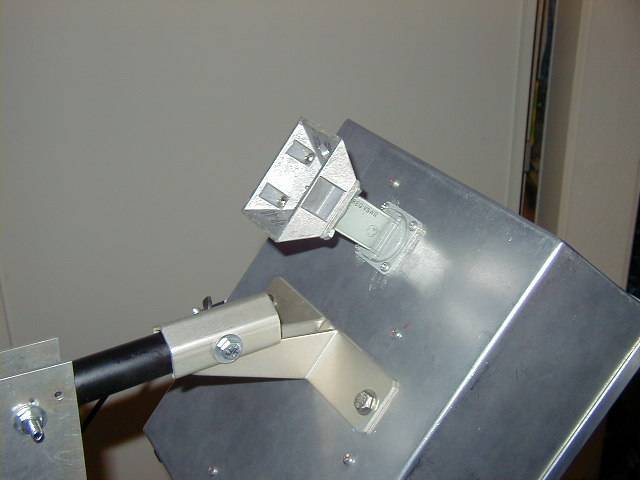
A closeup of the feed - Image 1
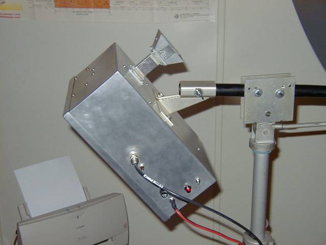
Side view showing connectors, etc - Image 1
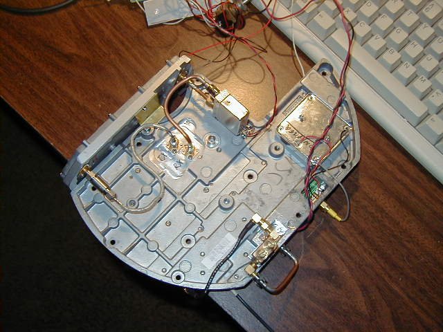
The inside of the transverter box - Image 1
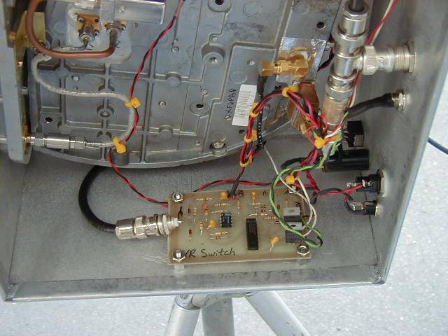
To automate the switching between transmit and receive on the transmitter (a signal must be pulled low on the Qualcomm board and a relay energized), I built a simple TR switching board designed by Chuck, WB6IGP. This senses the RF energy present on the IF line of the transverter and switches two FETs. At the moment I have this board connected to the IF line with a coax T which is probably not the ideal way to do it. Someday I will probably improve this.
The TR switch board installed - Image 1
6/6/00 - I bought a Kenwood TR-9000 2m all-mode rig to use as an IF transceiver to allow me to work FM and SSB on 10 ghz and also on 2m around town. The output power of the rig has been reduced from 10W to 10-20mW to work with my transverter. I have tested it and it works very well. The frequency display is made of red LEDs and apparently does not work well in bright sunlight. I have not experienced this yet but will probably have to make a sun shade of some sort for the contests.
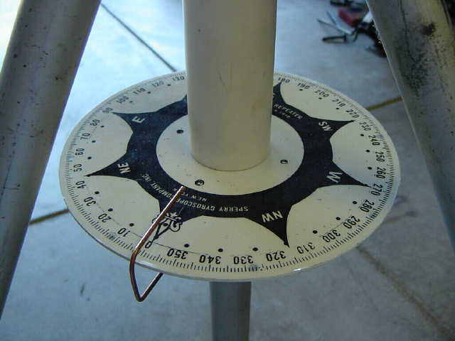
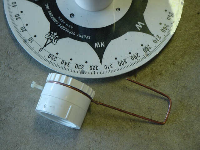
8/27/00 - I finally added a compass rose to the tripod for contesting and got some pictures of it taken (sometime last month). Kerry N6IZW provided most of the assembly and I made the brazing rod indicator. The actual compass rose is printed on a piece of overhead projector slide material which is glued to an aluminum disc. PVC fittings hold everything together along with a couple set screws. Thanks Kerry for coming up with the design and providing parts.
The compass rose assembly - Image 1, Image 2
I have also modified a Qualcomm board to function as an 1152 MHz LO and marker generator for all the ham bands 1152 and up. These modifications are detailed here. The 1152 board generates an LO at 1152 which is very rich in harmonics. I can pick up the 10368 MHz multiple from over a block away with only a short stub for an antenna on the 1152 board. This board is very useful for making sure the rig is working on receive when I don't have a beacon I can listen to easily.
The 1152 board - Image 1
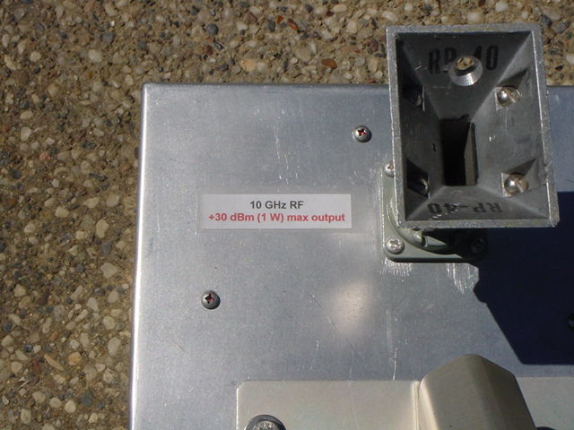
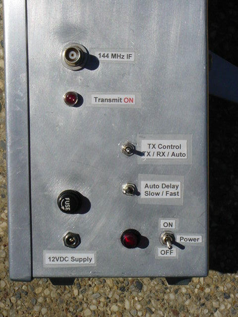
I finally added labels for the controls. These won't last long but were useful during the contest.
Waveguide output label - Image 1
Side panel controls labels - Image 1,
Image 2
Next up: Investigate TR switch misfires in heavy RFI environments? Move everything back to San Diego.