A 24GHz Gunnplexer
Wide-Band FM Transceiver
Jeff Keyzer, KF6PBP


News (4/14/00): I have finally finished the transceiver and had time to get some pictures and information up on this page.
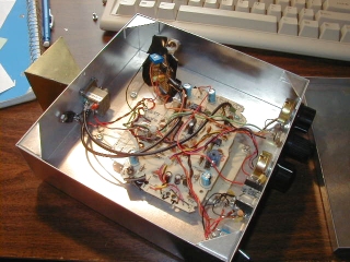
To turn a gunnplexer into a full transceiver, only a couple additional components are necessary. One is a 30 MHz receiver kit, available from Ramsey Electronics (look for the FR-10 under Amateur Radio Gear). This kit is easy to build, costs $34.95, and requires only a few small modifications before it can be used in this project. The next major component necessary is a modulator board which amplifies signals from an electret microphone and uses them to modulate the varactor diode voltage. This allows the transmission of FM signals. The other components include an RF tight case, a horn antenna, a couple regulators, and various knobs and switches.
The resulting transceiver is capable of communication over several miles LOS with a simple horn antenna, in decent weather. (Water vapor quickly attenuates 24 GHz signals.) Two frequencies are commonly used in Southern California, 24.155 GHz and 24.125 GHz. One station transmits on one frequency and the other picks the remaining frequency. The difference between the frequencies is 30 MHz which is received by the Ramsey receiver. These transceivers allow full-duplex communication and the ability to hear oneself while talking, much like a telephone.
Remove FL2 (450 khz filter), replace with 0.01uF disc cap.
This makes passband 100 kHz wide.
Shunt resistor R14 (33k) with a 3.9k resistor on the bottom of the PC board.
This broadens passband to about 200 kHz.
Reduce tuning range from 5 MHz to 500 kHz by removing C12 (56pF) and replacing it with a 15pF disc cap. Add a second 15pF disc cap under the PC board across L3, the oscillator coil.
Replace 10k pot R10 with a 10-turn 10K pot and calibrated readout dial.